Uart Wiring Diagram

Rj11 Socket Wiring Diagram Australia, How to punch down an RJ11 Telephone Jack, 6.36 MB, 04:38, 387,634, CableSupply.com, 2009-08-05T00:16:07.000000Z, 19, Rj11 Socket Wiring Diagram Australia | Computacion, Redes de computadoras, Computadoras, www.pinterest.com.mx, 728 x 783, jpeg, rj11 wiring rj45 diagram cable ethernet usb jack pinout adapter cat5 female male convert using rs485 cat wires code socket, 20, rj11-socket-wiring-diagram-australia, Anime Arts
Ezo tm orp circuit wiring diagram revised 11/30/17 to connect an ezo tm circuit to your microcontroller, follow the diagram below. Make sure the ezo tm circuit and microcontroller share a common ground. The eight channels of uart are called as octal of uart. The first pc uart, 8250, was manufactured by national semiconductors.
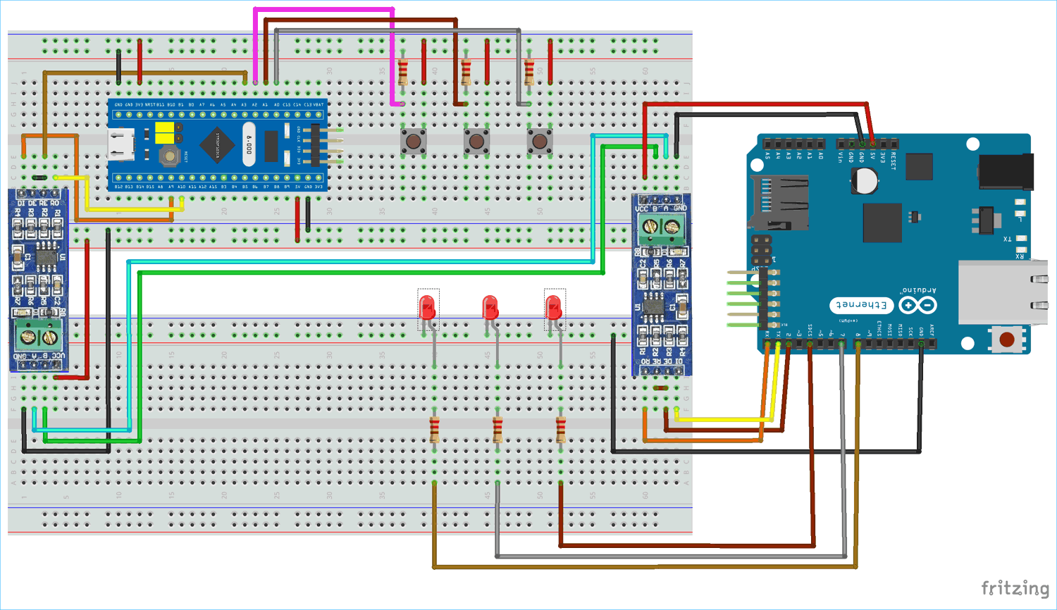
The pin diagram of 8050 is shown in fig. 9. 86 (a) and its schematic pin diagram is depicted in fig. 9. 86 (b). The block diagram of 8250 uart is shown in fig, 9. 87. Usb to uart using mcp2200 3 circuit ideas i electronic diy projects robotics ft232r driver with arduino interfacing w software on the computer forum çift vurgu i̇stemek serial converter tillsonburgkiwanis com ftdi cables components silicon labs cp2102 module circuitstate electronics cable rs232 pinout features datasheet application notes and circuits for pcb ttl. Usb to rs422 uart serial converter pcb under repository circuits 38350 next gr. Pic ing the max3100 adding usb to a microcontroller using uart. Usb uart click breakout board for ft232rl chip. Rs485 to uart convension circuit. Building a usb uart serial adapter blog single board computers element14 community.
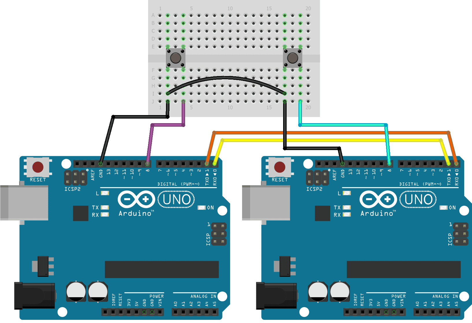
How to Set Up UART Communication on the Arduino - Circuit Basics

Single Wire UART - GHI Electronics' Forums

Usb To Uart Cable Wiring Diagram | USB Wiring Diagram

Wiring and Flashing the ESP8266 Firmware via TTL UART Bridge | 14core.com

Usb To Uart Cable Wiring Diagram | USB Wiring Diagram

Arduino Uno Uart Pinout - Pcb Circuits

Serial Communication - learn.sparkfun.com
uart cable - GSM-Forum
Usb To Uart Cable Wiring Diagram | USB Wiring Diagram

Usb To Uart Cable Wiring Diagram | USB Wiring Diagram
